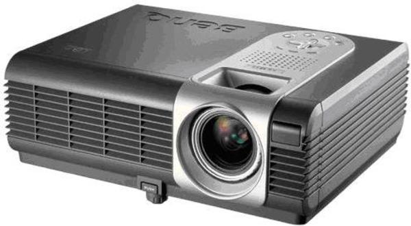
Your guide to replacing the BenQ W100 projector lamp
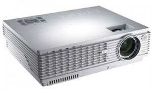 Follow our quick guide to replace the BenQ 5J.J1S01.001 lamp in your BenQ W100 projector.

Go with authentic
Your BenQ W100 projector is a sophisticated machine with sensitive electronic components. The BenQ 5J.J1S01.001 projector lamp has been designed specifically to keep your projector operating at optimum levels.
You’ll want to install an authentic BenQ 5J.J1S01.001 lamp to keep your BenQ W100 projector working properly and to get the best picture quality. Although cheaper at first, generic knock-off lamps are actually not that great a bargain. These so-called “compatible” lamps are prone to explosion, have poor illumination, a shorter lamp life and can cause permanent damaged to the sensitive electronic components in your BenQ W100 projector.
Copy-cat manufacturers simply don’t have the parts or the know-how to create a proper projector lamp so create their lamps using toxic substances such as Krypton-85. Don’t compromise your health and void your warranty to save a few extra dollars. Go with an authentic BenQ 5J.J1S01.001 OEM lamp sold by a dependable seller and keep your BenQ W100 projector working. Learn the 7 Ways to spot a counterfeit lamp.
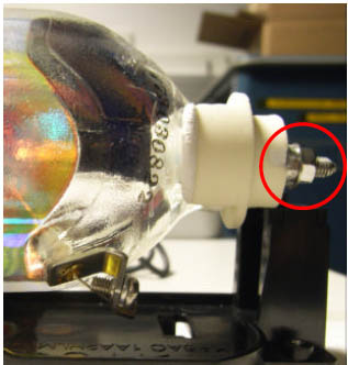
Looking for the less expensive, eco-friendly option? Want more information? Watch our step-by-step video on replacing only the BenQ 5J.J1S01.001 bulb instead of the entire lamp housing.
Replacement messages for the BenQ 5J.J1S01.001 lamp
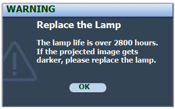
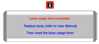
You’ll have plenty of notice when it’s time to replace the BenQ 5J.J1S01.0011 lamp. When it approaches end of life the BenQ W100 projector’s lamp indicator will light red and the following warning messages will appear on screen.
You’ll have plenty of notice when it’s time to replace the BenQ 5J.J1S01.0011 lamp. When it approaches end of life the BenQ W100 projector’s lamp indicator will light red and the following warning messages will appear on screen.
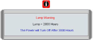
First Warning: TheBenQ 5J.J1S01.001 lamp has been in operation for 2800 hours. If you have turned on Economy Mode, on your BenQ W100 projector, you can continue using the lamp until it reaches 2950 hours of usage.
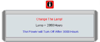
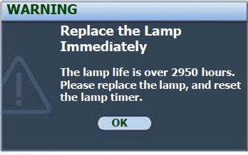
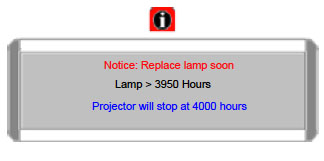
Second Warning: The BenQ 5J.J1S01.001 lamp has been in operation for 2950 hours. Replace the lamp as soon as possible to keep the BenQ W100 projector working at optimum levels.
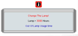
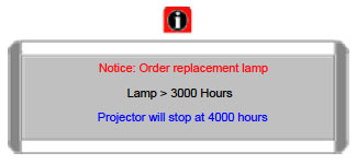
Third warning: The BenQ 5J.J1S01.001 lamp has been in operation for 3000 hours. You’ll see this message for 30 seconds along with the LAMP indicator lighting up red for 40 seconds. Replace the lamp immediately before using the BenQ W100 projector.
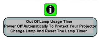
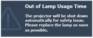
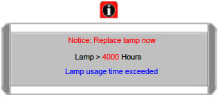
Final warning: You’re out of time! The BenQ 5J.J1S01.001 has reached end of life. The projector will shutdown in 40 seconds. The lamp MUST be replaced immediately before the BenQ MP720 projector will turn back on.
Replacing the BenQ 5J.J1S01.001 lamp
Before changing the lamp:
- Reduce the risk of electrical shock by disconnecting the power cord on the BenQ W100 projector.
- Reduce the risk of severe burns by allowing the projector to cool for at least 45 minutes. The BenQ W100 operates under high temperatures and needs time to coll.
- Turn the power off and disconnect the BenQ W100 projector.
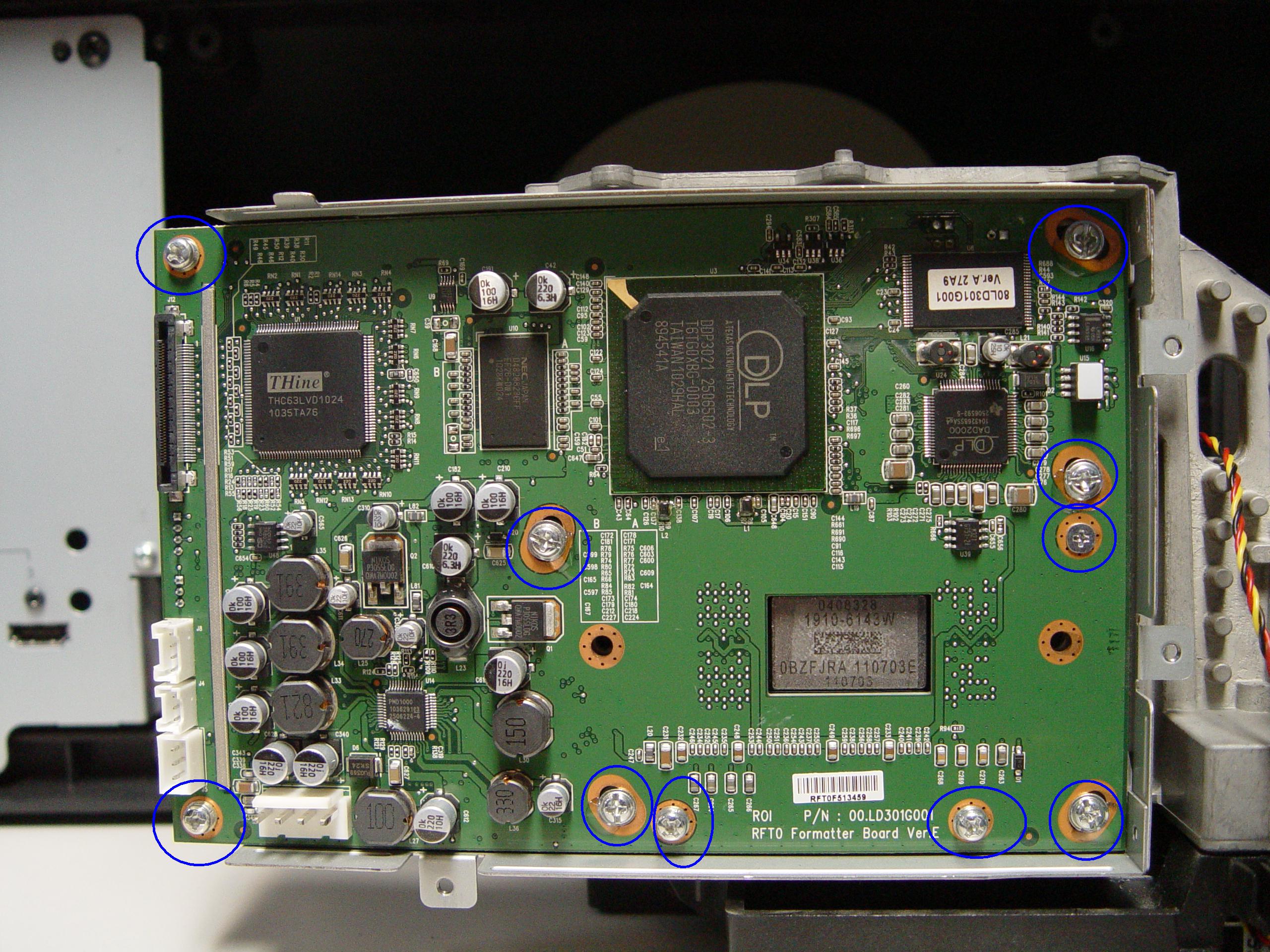
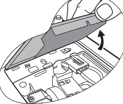
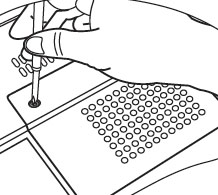
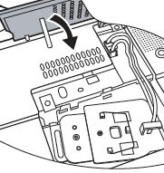
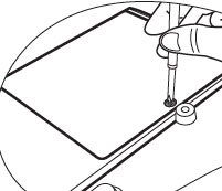
- The lamp cover is found on the bottom of the projector. Turn the projector over and loosen screw holding the BenQ W100 lamp cover in place. (Use a magnetic screwdriver to make the whole process easier.)

- Remove the lamp cover from the BenQ W100 projector.
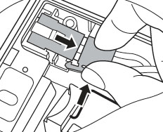
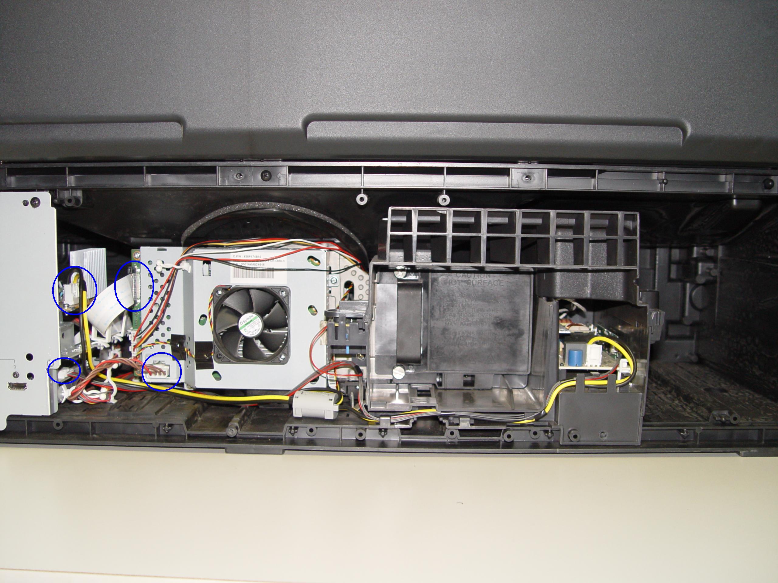
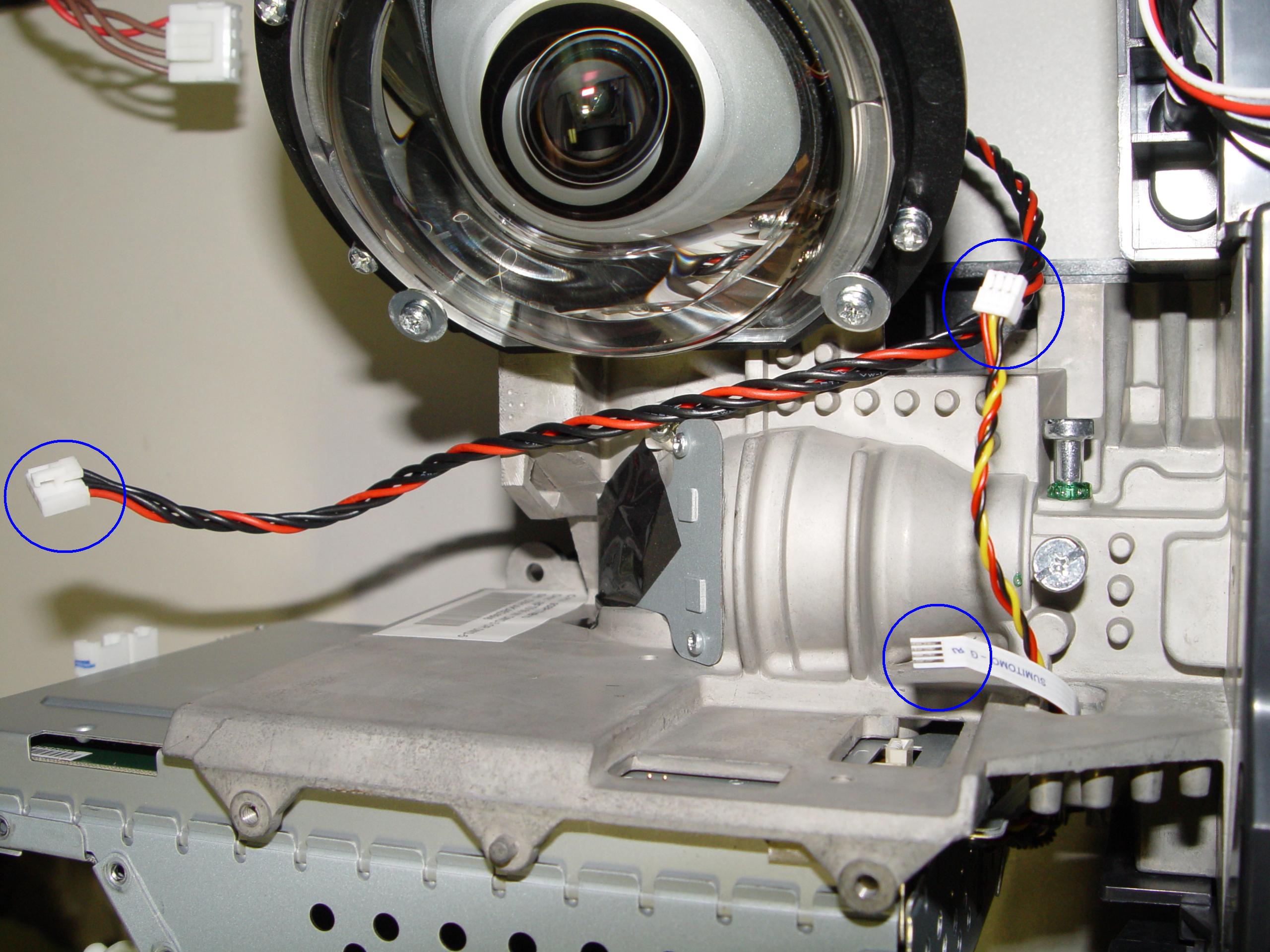
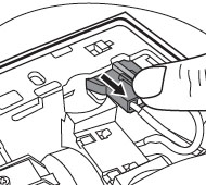
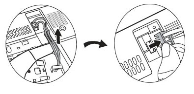
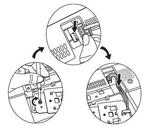
- Loosen the connectors on the BenQ 5J.J1S01.001 lamp. Don’t try to lift out the lamp until the connectors have been released.
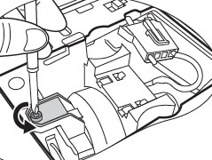
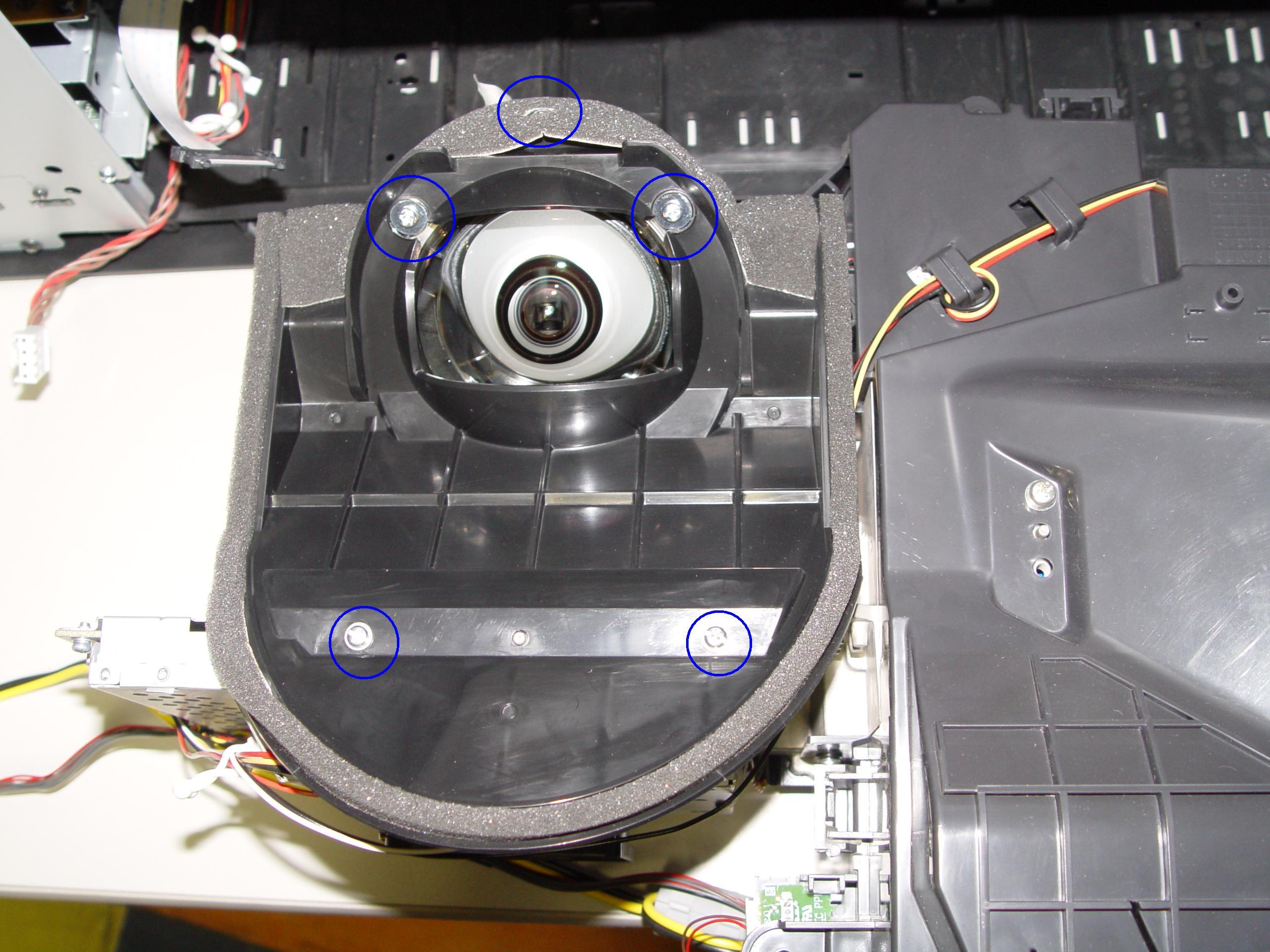
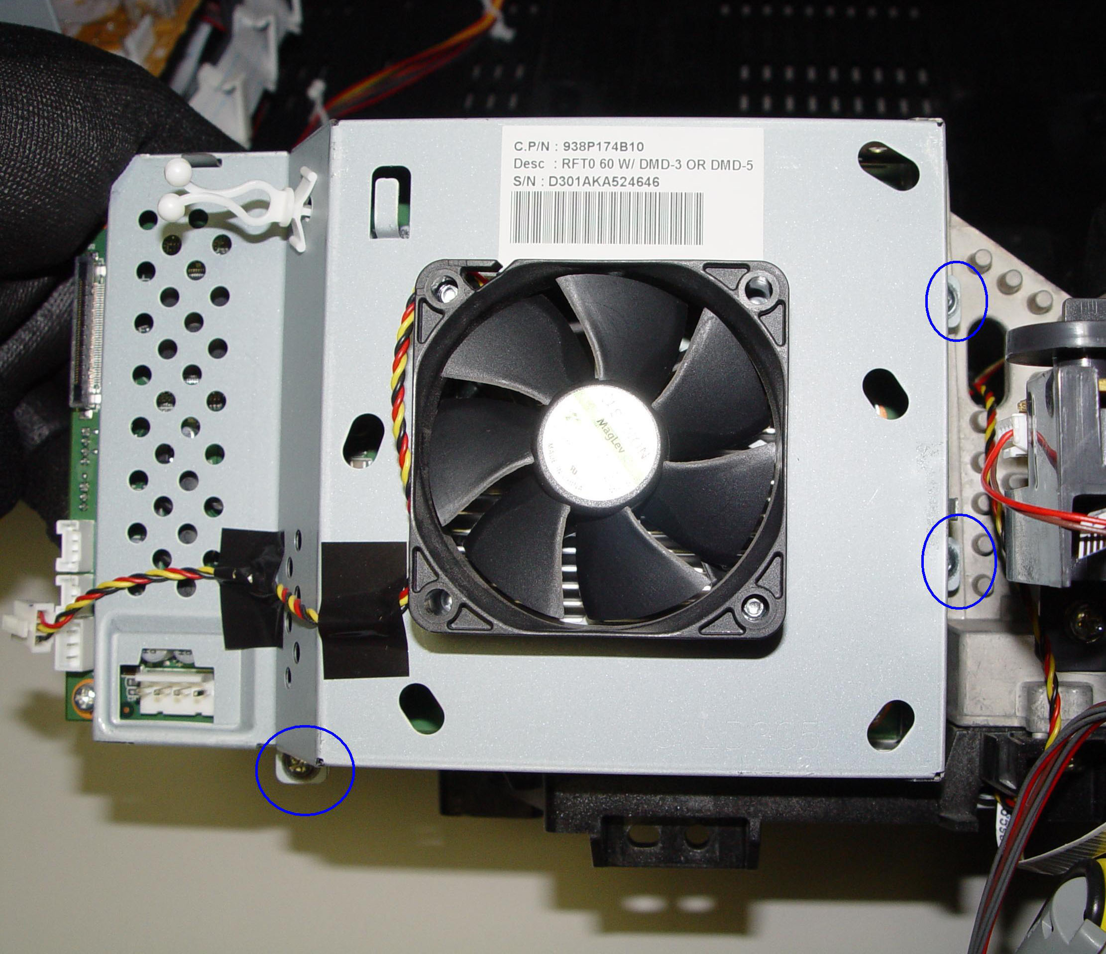
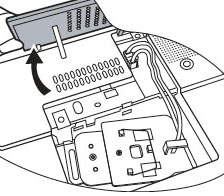
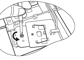
- Loosen the screw holding the BenQ 5J.J1S01.001 lamp in place. Be sure not the lose the screw!
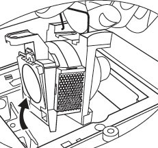
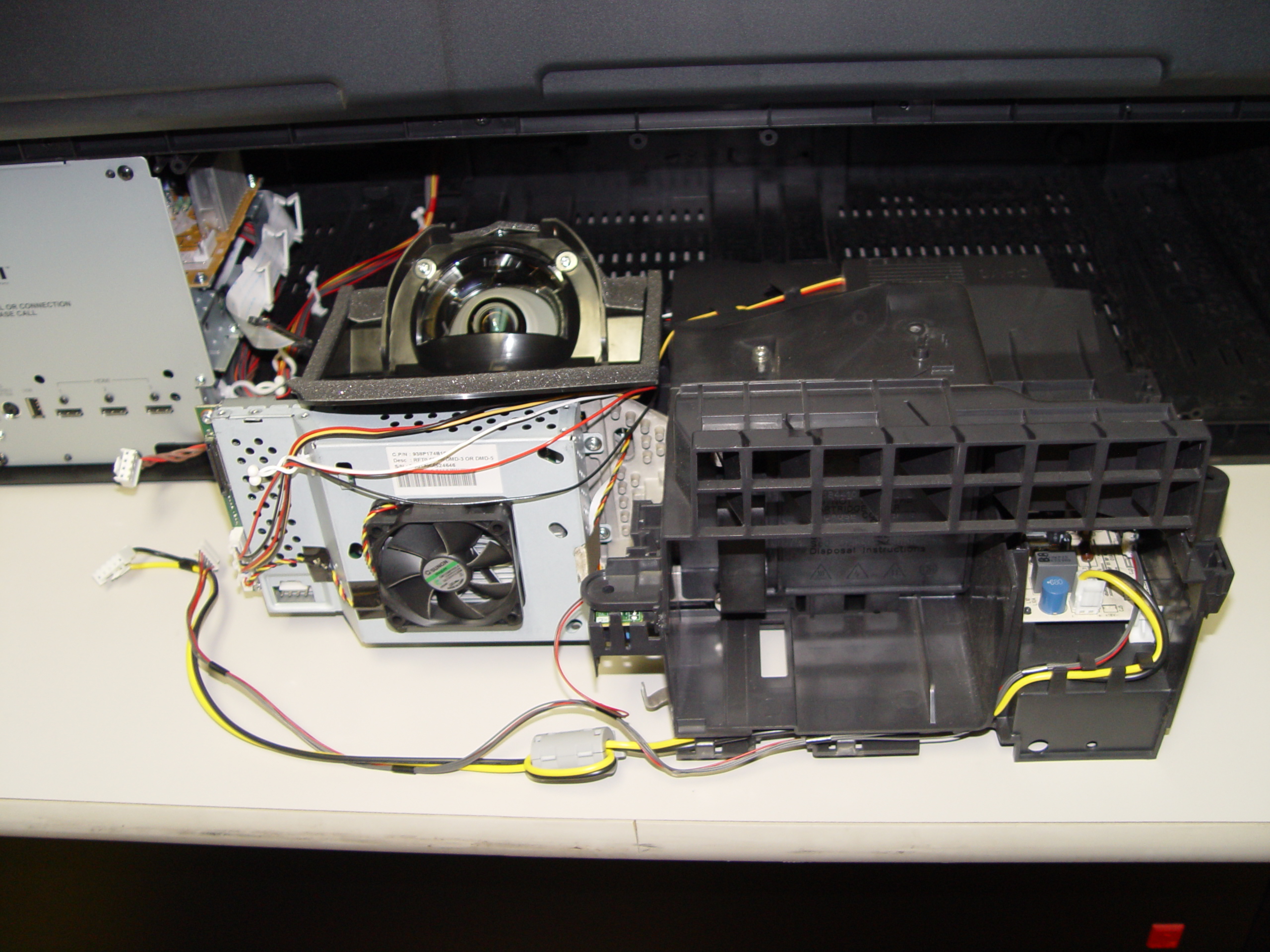
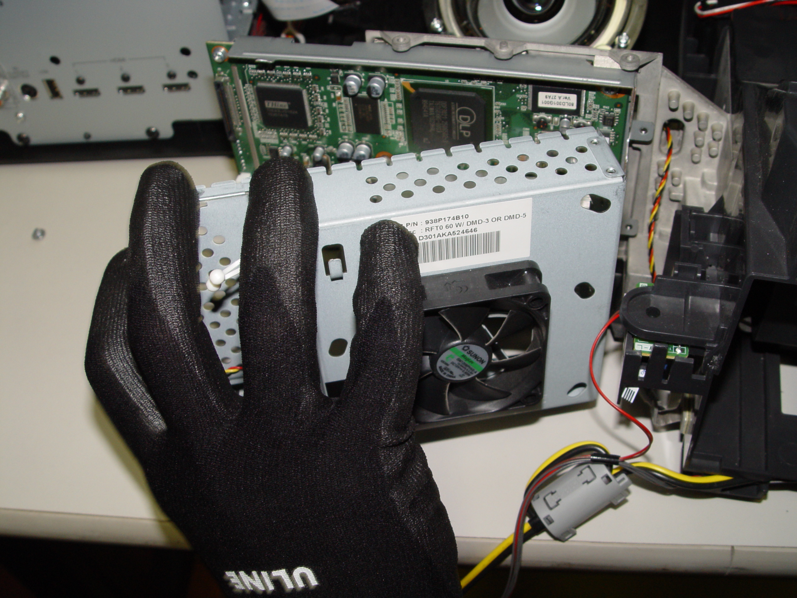
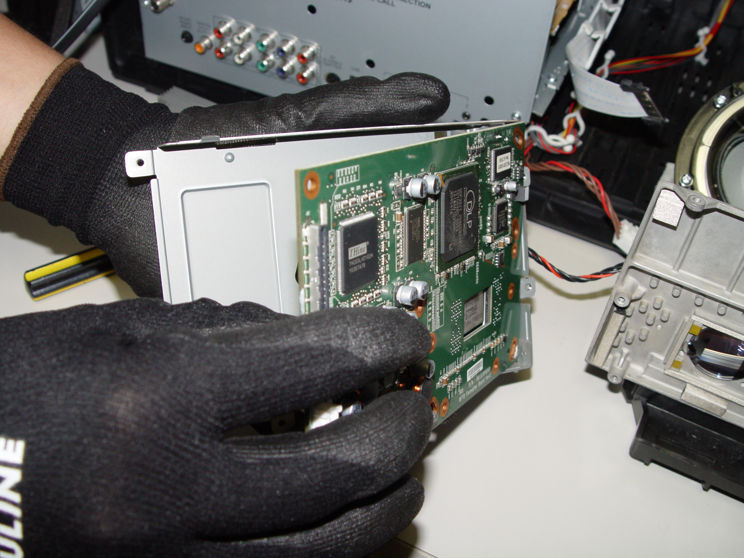
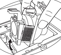
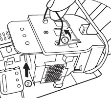
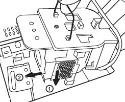
- Grab the wire handle on the BenQ 5J.J1S01.001 lamp so it lifts up. Slowly and gently pull the BenQ 5J.J1S01.001 lamp out of the projector. Pulling too quickly can cause the bulb to shatter. Learn what to do when the bulb breaks.
- Avoid touching the optical components inside the BenQ W100 projector as this can leave marks on the lenses causing image distortion and unwanted color changes.
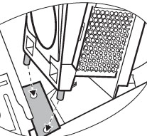
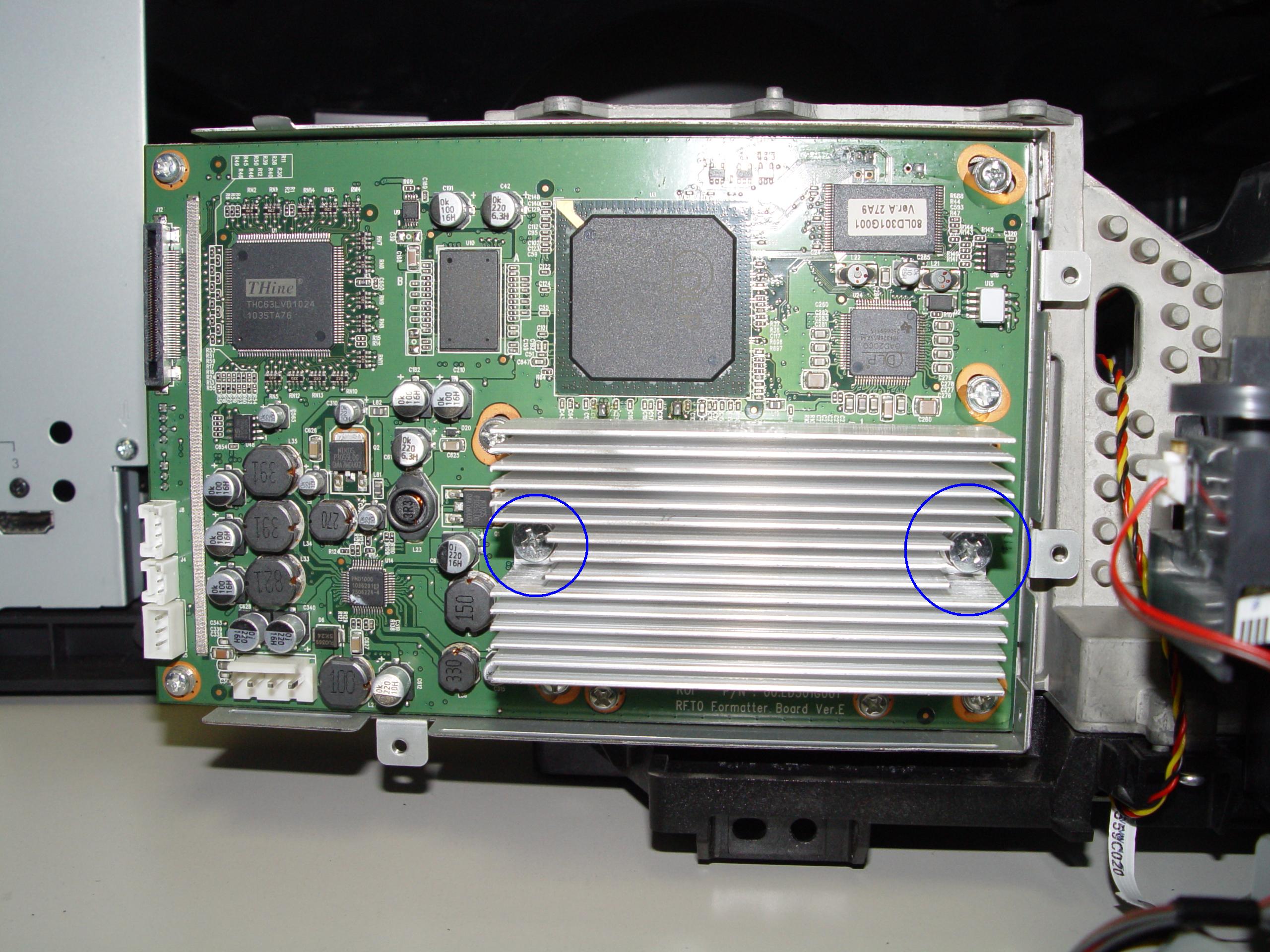
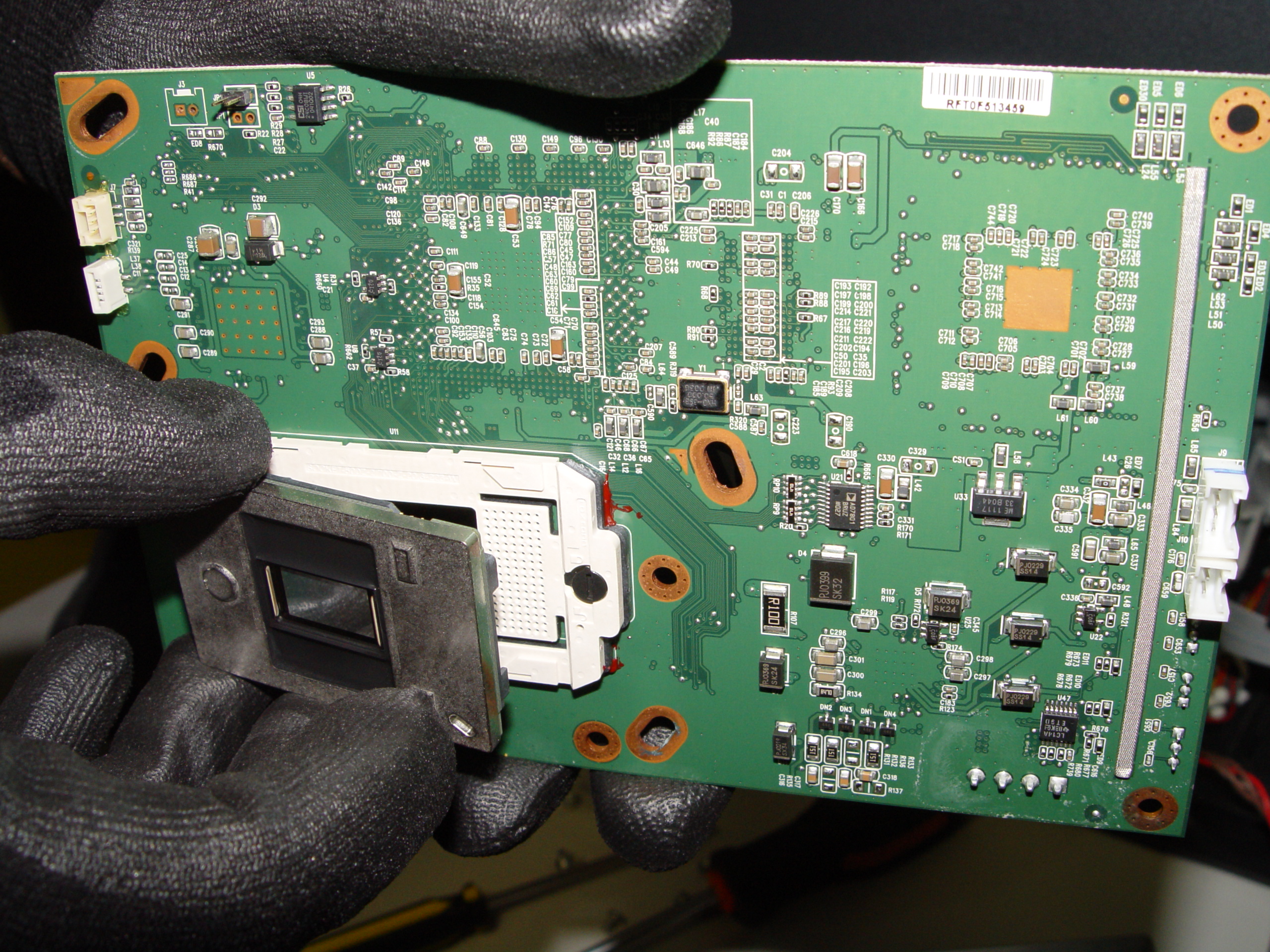
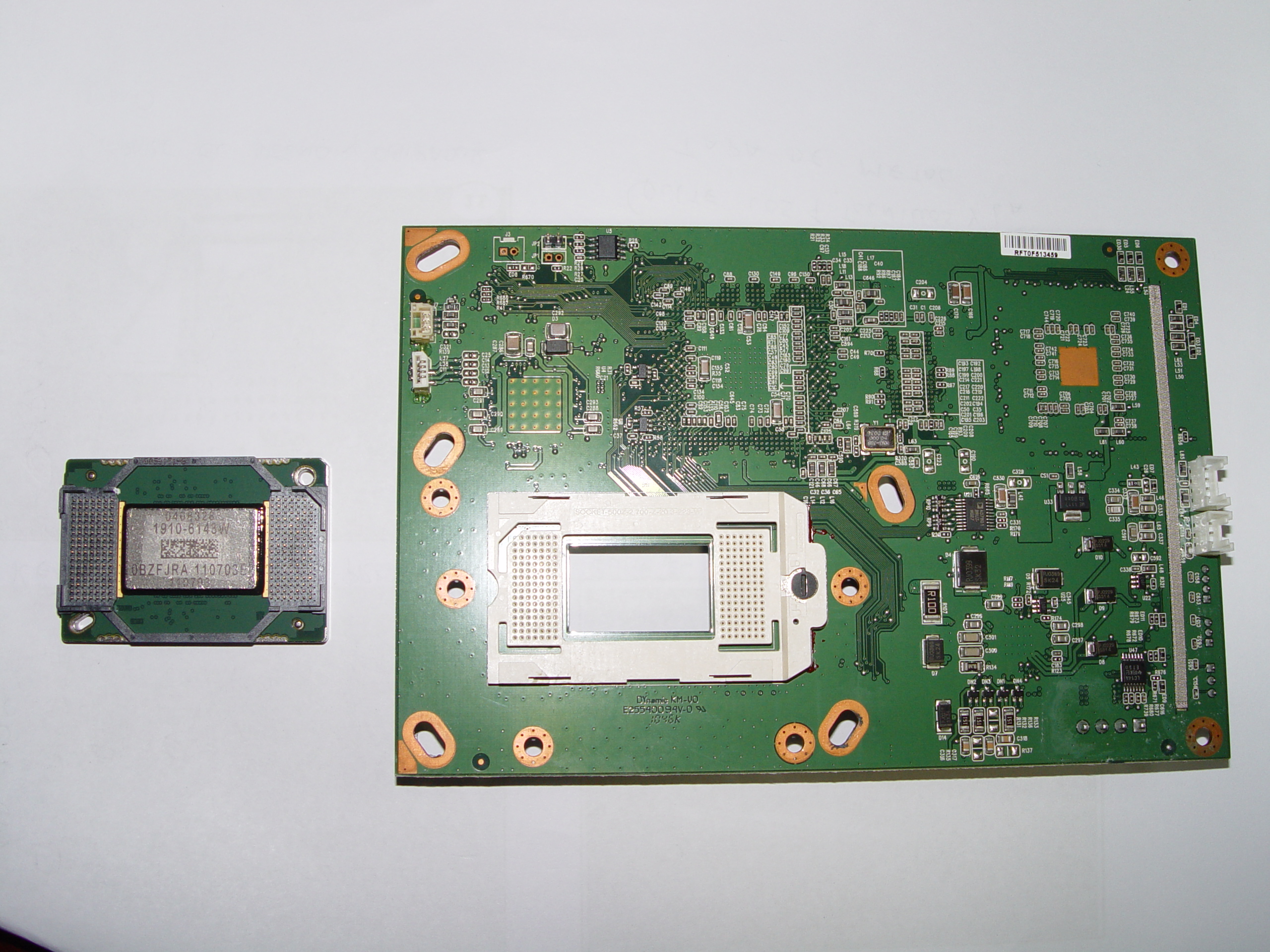
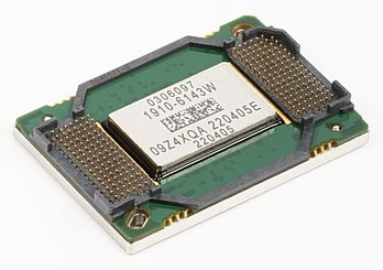
- Hold the new BenQ 5J.J1S01.001 lamp by the sides and align the two locators on the bottom of the lamp with the holes in the BenQ W100 projector lamp (they look like little feet). Push the BenQ 5J.J1S01.001 lamp down all the way into the projector.
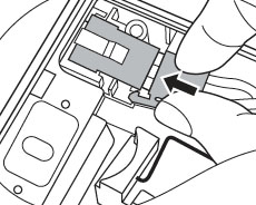
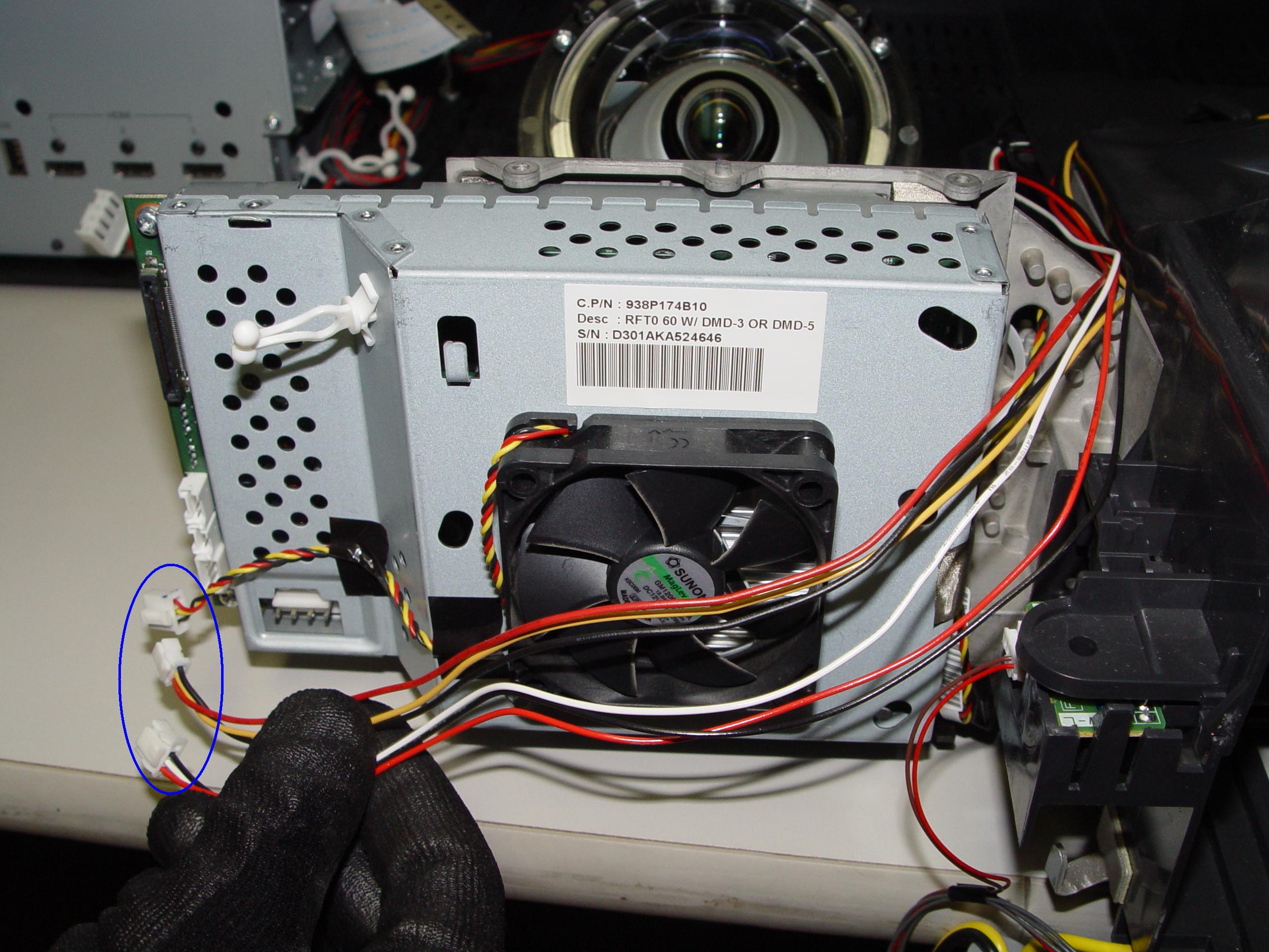
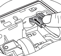
- Re-attach the BenQ 5J.J1S01.001 lamp connector into the BenQ W100 projector.
- Tighten the screw on the newly installed BenQ 5J.J1S01.001 lamp.

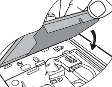
- Install the BenQ W100 projector lamp cover.
- Tighten the screw on the lamp cover.
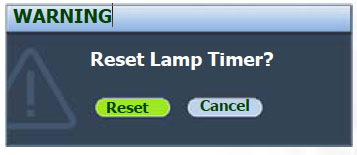
- Reset the lamp timer.
NOTE: The BenQ 5J.J1S01.001 lamp contains mercury and should not be thrown into regular garbage. Recycle your used lamps! If you bought from an authentic manufacturer they will recycle the lamp for you at no extra cost (another reason to buy authentic lamps).
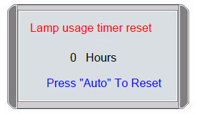
Resetting the Lamp Hour Timer
It’s important to only reset the lamp timer when the BenQ 5J.J1S01.001 lamp has been replaced. Resetting the lamp timer without changing the BenQ 5J.J1S01.001 lamp can cause significant harm to your BenQ W100 projector.
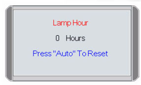
- Press and hold the Exit 5 button on the BenQ W100 projector for 5 seconds to display the total used lamp time.
- Press Auto on the projector or on the remote control to reset the Lamp Hour to “0”.
- Wait about 5 seconds to let the on screen display (OSD) disappear.
- Only reset the Lamp Hour when a new lamp has been installed in order that the life BenQ 5J.J1S01.001 can be properly tracked and prevent the projector shutting down unexpectedly.
Extending the life of the BenQ 5J.J1S01.001 lamp:
- Keep your air filters clean to avoid overheating the projector.
- Use the Lamp Power option on the BenQ W100 projector and set to Economic Mode to reduce the amount of power used but extend lamp life.
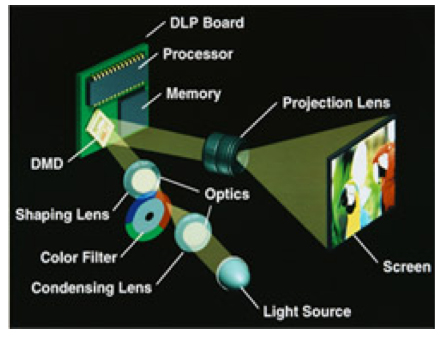
- Learn more with Top tips for extending DLP projector lamp life.